Interfaces
Physical and virtual interfaces allow traffic to flow between internal networks, and between the internet and internal networks. FortiOS has options for configuring interfaces and groups of sub-networks that can scale as your organization grows. The following table lists commonly used interface types.
Interface type | Description |
|---|---|
Physical | A physical interface can be connected to with either Ethernet or optical cables. Depending on the FortiGate model, there is a varying number of Ethernet or optical physical interfaces. Some FortiGates have a grouping of interfaces labeled as lan that have a built-in switch functionality. See Physical interface for more information. |
VLAN | A virtual local area network (VLAN) logically divides a local area network (LAN) into distinct broadcast domains using IEEE 802.1Q VLAN tags. A VLAN interface supports VLAN tagging and is associated with a physical interface that can be connected to a device, such as a switch or a router that supports these tags. VLANs can be used on a FortiGate in NAT or transparent mode, and the FortiGate functions differently depending on the operation mode See VLAN for more information. |
Aggregate | An aggregate interface uses a link aggregation method to combine multiple physical interfaces to increase throughput and to provide redundancy. FortiOS supports a link aggregation (LAG) interface using the Link Aggregation Control Protocol (LACP) based on IEEE 802.3ad/802.1ax. See Aggregation and redundancy for more information. |
Redundant | A redundant interface combines multiple physical interfaces where traffic only uses one of the interfaces at a time. Its primary purpose is to provide redundancy. This interface is typically used with a fully-meshed HA configuration. See Aggregation and redundancy for more information. |
Loopback | A loopback interface is a logical interface that is always up because it has no physical link dependency, and the attached subnet is always present in the routing table. It can be accessed through several physical or VLAN interfaces. See Loopback interface for more information. |
Software switch | A software switch is a virtual switch interface implemented in firmware that allows member interfaces to be added to it. Devices connected to member interfaces communicate on the same subnet, and packets are processed by the FortiGate’s CPU. A software switch supports adding a wireless SSID as a member interface. See Software switch for more information. |
Hardware switch | A hardware switch is a virtual switch interface implemented at the hardware level that allows member interfaces to be added to it. Devices connected to member interfaces communicate on the same subnet. A hardware switch relies on specific hardware to optimize processing and supports the Spanning Tree Protocol (STP). See Hardware switch for more information. |
Zone | A zone is a logical group containing one or more physical or virtual interfaces. Grouping interfaces in zones can simplify firewall policy configurations. See Zone for more information. |
Virtual wire pair | A virtual wire pair (VWP) is an interface that acts like a virtual wire consisting of two interfaces, with an interface at each of the wire. No IP addressing is configured on a VWP, and communication is restricted between the two interfaces using firewall policies. See Virtual wire pair for more information. |
FortiExtender WAN extension | A FortiExtender WAN extension is a managed interface that allows a connected FortiExtender to provide WAN connectivity to the FortiGate. See FortiExtender for more information. |
FortiExtender LAN extension | A FortiExtender LAN extension is a managed interface that allows a connected FortiExtender to provide LAN connectivity to the FortiGate. See FortiExtender for more information. |
Enhanced MAC VLAN | An enhanced media access control (MAC) VLAN, or EMAC VLAN, interface allows a physical interface to be virtually subdivided into multiple virtual interfaces with different MAC addresses. In FortiOS, the EMAC VLAN functionality acts like a bridge. See Enhanced MAC VLAN for more information. |
VXLAN | A Virtual Extensible LAN (VXLAN) interface encapsulates layer 2 Ethernet frames within layer 3 IP packets and is used for cloud and data center networks. See VXLAN for more information. |
Tunnel | A tunnel virtual interface is used for IPsec interface-based or GRE tunnels and are created when configuring IPsec VPN and GRE tunnels, respectively. The tunnel interface can be configured with IP addresses on both sides of the tunnel since this is a requirement when using a tunnel interface with a dynamic routing protocol. See OSPF with IPsec VPN for network redundancy, GRE over IPsec, and Cisco GRE-over-IPsec VPN for more information. |
WiFi SSID | A WiFi SSID interface is used to control wireless network user access to a wireless local radio on a FortiWiFi or to a wireless access point using a FortiAP. The SSID is created using the WiFi & Switch Controller > SSIDs page, and it appears in the Network > Interfaces page once it is created. See Defining a wireless network interface (SSID) in the FortiWiFi and FortiAP Configuration Guide for more information. |
VDOM link | A VDOM link allows VDOMs to communicate internally without using additional physical interfaces. See Inter-VDOM routing for more information. |
Interface settings
Administrators can configure both physical and virtual FortiGate interfaces in Network > Interfaces. There are different options for configuring interfaces when FortiGate is in NAT mode or transparent mode.
The available options will vary depending on feature visibility, licensing, device model, and other factors. The following list is not comprehensive.
To configure an interface in the GUI:
Go to Network > Interfaces.
Click Create New > Interface.
Configure the interface fields:
Interface Name
Physical interface names cannot be changed.
Alias
Enter an alternate name for a physical interface on the FortiGate unit. This field appears when you edit an existing physical interface. The alias does not appear in logs.
The maximum length of the alias is 25 characters.
Type
The configuration type for the interface, such as VLAN, Software Switch, 802.3ad Aggregate, and others.
Interface
This field is available when Type is set to VLAN.
Select the name of the physical interface that you want to add a VLAN interface to. Once created, the VLAN interface is listed below its physical interface in the Interface list.
You cannot change the physical interface of a VLAN interface.
VLAN ID
This field is available when Type is set to VLAN.
Enter the VLAN ID. The VLAN ID can be any number between 1 and 4094 and must match the VLAN ID added by the IEEE 802.1Q-compliant router or switch that is connected to the VLAN subinterface.
The VLAN ID can be edited after the interface is added.
VRF ID
Virtual Routing and Forwarding (VRF) allows multiple routing table instances to coexist on the same router. One or more interface can have a VRF, and packets are only forwarded between interfaces with the same VRF.
Virtual Domain
Select the virtual domain to add the interface to.
Only administrator accounts with the super_admin profile can change the Virtual Domain.
Interface Members
This section can have different formats depending on the Type.
Members can be selected for some interface types:
Software Switch or Hardware Switch: Specify the physical and wireless interfaces joined into the switch.
802.3ad Aggregate or Redundant Interface: This field includes the available and selected interface lists.
Role
Set the role setting for the interface. Different settings will be shown or hidden when editing an interface depending on the role:
LAN: Used to connected to a local network of endpoints. It is default role for new interfaces.
WAN: Used to connected to the internet. When WAN is selected, the Estimated bandwidth setting is available, and the following settings are not: DHCP server, Create address object matching subnet, Device detection, Security mode, One-arm sniffer, Dedicate to extension/fortiap modes, and Admission Control.and will show Estimated Bandwidth settings.
DMZ: Used to connected to the DMZ. When selected, DHCP server and Security mode are not available.
Undefined: The interface has no specific role. When selected, Create address object matching subnet is not available.
Estimated bandwidth
The estimated WAN bandwidth.
The values can be entered manually, or saved from a speed test executed on the interface. The values can be used in SD-WAN rules that use the Maximize Bandwidth or Best Quality strategy.
Traffic mode
This option is only available when Type is WiFi SSID.
Tunnel: Tunnel to wireless controller
Bridge: Local bridge with FortiAP's interface
Mesh: Mesh downlink
Address
Addressing mode
Select the addressing mode for the interface.
Manual: Add an IP address and netmask for the interface. If IPv6 configuration is enabled, you can add both an IPv4 and an IPv6 address.
DHCP: Get the interface IP address and other network settings from a DHCP server.
Auto-managed by IPAM: Assign subnets to prevent duplicate IP addresses from overlapping within the same Security Fabric. See Configure IPAM locally on the FortiGate.
PPPoE: Get the interface IP address and other network settings from a PPPoE server. This option is only available on entry-level FortiGate models.
One-Arm Sniffer: Set the interface as a sniffer port so it can be used to detect attacks. See One-arm sniffer.
IP/Netmask
If Addressing Mode is set to Manual, enter an IPv4 address and subnet mask for the interface. FortiGate interfaces cannot have multiple IP addresses on the same subnet.
IPv6 addressing mode
Select the addressing mode for the interface:
Manual: Add an IP address and netmask for the interface.
DHCP: Get the interface IP address and other network settings from a DHCP server.
Delegated: Select an IPv6 upstream interface that has DHCPv6 prefix delegation enabled, and enter an IPv6 subnet if needed. The interface will get the IPv6 prefix from the upstream DHCPv6 server that is connected to the IPv6 upstream interface, and form the IPv6 address with the subnet configured on the interface.
IPv6 Address/Prefix
If Addressing Mode is set to Manual and IPv6 support is enabled, enter an IPv6 address and subnet mask for the interface. A single interface can have an IPv4 address, IPv6 address, or both.
Auto configure IPv6 address
Automatically configure an IPv6 address using Stateless Address Auto-configuration (SLAAC).
This option is available when IPv6 addressing mode is set to Manual.
DHCPv6 prefix delegation
Enable/disable DHCPv6 prefix delegation, which can be used to delegate IPv6 prefixes from an upstream DHCPv6 server to another interface or downstream device.
When enabled, there is an option to enable a DHCPv6 prefix hint that helps the DHCPv6 server provide the desired prefix.
Create address object matching subnet
This option is available and automatically enabled when Role is set to LAN or DMZ.
This creates an address object that matches the interface subnet and dynamically updates the object when the IP/Netmask changes.
See Interface subnet for more information.
Secondary IP Address
Add additional IPv4 addresses to this interface.
Administrative Access
IPv4 Administrative Access
Select the types of administrative access permitted for IPv4 connections to this interface. See Configure administrative access to interfaces.
IPv6 Administrative Access
Select the types of administrative access permitted for IPv6 connections to this interface. See Configure administrative access to interfaces.
DHCP Server
Enable a DHCP server for the interface. See DHCP servers and relays.
Stateless Address Auto-configuration (SLAAC)
Enable to provide IPv6 addresses to connected devices using SLAAC.
DHCPv6 Server
Select to enable a DHCPv6 server for the interface.
When enabled, you can configure DNS service settings: Delegated (delegate the DNS received from the upstream server), Same as System DNS, or Specify (up to four servers).
You can also enable Stateful serverto configure the DHCPv6 server to be stateful. Manually enter the IP range, or use Delegated mode to delegate IP prefixes from an upstream DHCPv6 server connected to the upstream interface.
Network
Device Detection
Enable/disable passively gathering device identity information about the devices on the network that are connected to this interface.
Security Mode
Enable/disable captive portal authentication for this interface. After enabling captive portal authentication, you can configure the authentication portal, user and group access, custom portal messages, exempt sources and destinations/services, and redirect after captive portal.
DSL Settings
Physical mode
Set to ADSL or VDSL.
Transfer mode
Set to PTM or ATM.
If the Transfer mode is set to ATM, the Virtual channel identification, Virtual path identification, ATM protocol, and MUX type can be configured.
Traffic Shaping
Outbound shaping profile
Enable/disable traffic shaping on the interface. This allows you to enforce bandwidth limits on individual interfaces. See Interface-based traffic shaping profile for more information.
Miscellaneous
Comments
Enter a description of the interface of up to 255 characters.
Status
Enable/disable the interface.
Enabled: The interface is active and can accept network traffic.
Disabled: The interface is not active and cannot accept traffic.
Click OK.
To configure an interface in the CLI:
config system interface edit <name> set vdom <VDOM_name> set mode {static | dhcp | pppoe} set ip <IP_address/netmask> set security-mode {none | captive-portal | 802.1X} set egress-shaping-profile <profile> set device-identification {enable | disable} set allowaccess {ping https ssh http snmp telnet fgfm radius-acct probe-response fabric ftm} set eap-supplicant {enable | disable} set eap-method {peap | tls} set eap-identity <identity> set eap-password <password> set eap-ca-cert <CA_cert> set eap-user-cert <user_cert> set secondary-IP enable config secondaryip edit 1 set ip 9.1.1.2 255.255.255.0 set allowaccess ping https ssh snmp http next end next endConfigure administrative access to interfaces
You can configure the protocols that administrators can use to access interfaces on the FortiGate. This helps secure access to the FortiGate by restricting access to a limited number of protocols. It helps prevent users from accessing interfaces that you don't want them to access, such as public-facing ports.
As a best practice, you should configure administrative access when you're setting the IP address for a port.
To configure administrative access to interfaces in the GUI:
Go to Network > Interfaces.
Create or edit an interface.
In the Administrative Access section, select which protocols to enable for IPv4 and IPv6 Administrative Access.
Industrial Connectivity
Allow Industrial Connectivity service access to proxy traffic between serial port and TCP/IP.
Available with FortiGate Rugged models equipped with a serial RS-232 (DB9/RJ45) interface and when Role is set to Undefined or WAN. See Industrial Connectivity.
Speed Test
Allow this interface to listen to speed test sender requests.
To allow the FortiGate to be configured as speed test server, configure the following:
config system global set speedtest-server {enable | disable} endFor more detail, see Running speed tests from the hub to the spokes in dial-up IPsec tunnels.
HTTPS
Allow secure HTTPS connections to the FortiGate GUI through this interface. If configured, this option is enabled automatically.
HTTP
Allow HTTP connections to the FortiGate GUI through this interface. This option can only be enabled if HTTPS is already enabled.
PING
The interface responds to pings. Use this setting to verify your installation and for testing.
FMG-Access
Allow FortiManager authorization automatically during the communication exchanges between FortiManager and FortiGate devices.
SSH
Allow SSH connections to the CLI through this interface.
SNMP
Allow a remote SNMP manager to request SNMP information by connecting to this interface.
FTM
Allow FortiToken Mobile Push (FTM) access.
RADIUS Accounting
Allow RADIUS accounting information on this interface.
Security Fabric Connection
Allow Security Fabric access. This enables FortiTelemetry and CAPWAP.
FEC implementations on 10G, 25G, 40G, and 100G interfaces
Only supported FEC (forward error correction) implementations are allowed to be configured on 10G, 25G, 40G, and 100G interfaces based on the speed that is selected.
For 1000M, 10G, or 40G interfaces, FEC is not supported and the option is disabled.
For 25G and 100G interfaces, FEC is automatically set to
cl91-rs-fecby default.
To configure an interface for FEC:
config system interface edit <name> set speed {10000full | 1000full | 100Gauto | 100Gfull | 25000auto | 25000full | 40000full} set mediatype {sr4 | lr4 | cr4} set forward-error-correction {disable | cl91-rs-fec | cl74-fc-fec} next endspeed {10000full | 1000full | 100Gauto | 100Gfull | 25000auto | 25000full | 40000full} | Set the interface speed:
|
mediatype {sr4 | lr4 | cr4} | Set the media type to use:
|
forward-error-correction {disable | cl91-rs-fec | cl74-fc-fec} | Set the forward error correction type:
|
Captive portals
A captive portal is used to enforce authentication before web resources can be accessed. Until a user authenticates successfully, any HTTP request returns the authentication page. After successfully authenticating, a user can access the requested URL and other web resources, as permitted by policies. The captive portal can also be configured to only allow access to members of specific user groups.
Captive portals can be hosted on the FortiGate or an external authentication server. They can be configured on any network interface, including VLAN and WiFi interfaces. On a WiFi interface, the access point appears open, and the client can connect to access point with no security credentials, but then sees the captive portal authentication page. See Captive Portal Security, in the FortiWiFi and FortiAP Configuration Guide for more information.
All users on the interface are required to authenticate. Exemption lists can be created for devices that are unable to authenticate, such as a printer that requires access to the internet for firmware upgrades.
 | When configuring a bridge mode SSID, you do not need to enable captive portal. |
To configure a captive portal in the GUI:
Go to Network > Interfaces and edit the interface that the users connect to. The interface Role must be LAN or Undefined.
Enable Security mode.
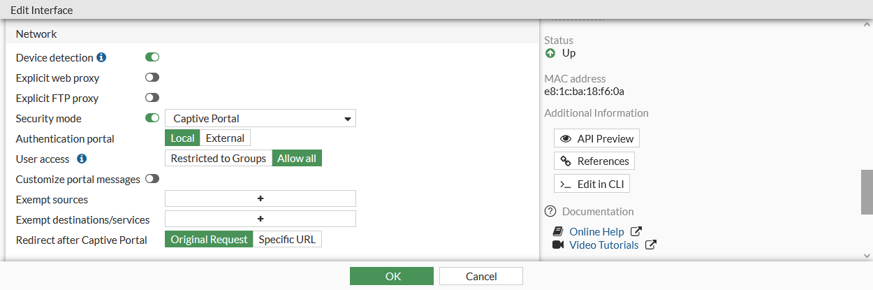
Configure the following settings, then click OK.
Authentication Portal
Configure the location of the portal:
Local: the portal is hosted on the FortiGate unit.
External: enter the FQDN or IP address of external portal.
User access
Select if the portal applies to all users, or selected user groups:
Restricted to Groups: restrict access to the selected user groups. The Login page is shown when a user tries to log in to the captive portal.
Allow all: all users can log in, but access will be defined by relevant policies. The Disclaimer page is shown when a user tried to log in to the captive portal.
Customize portal messages
Enable to use custom portal pages, then select a replacement message group. See Custom captive portal pages.
Exempt sources
Select sources that are exempt from the captive portal.
Each exemption is added as a rule in an automatically generated exemption list.
Exempt destinations/services
Select destinations and services that are exempt from the captive portal.
Each exemption is added as a rule in an automatically generated exemption list.
Redirect after Captive Portal
Configure website redirection after successful captive portal authentication:
Original Request: redirect to the initially browsed to URL .
Specific URL: redirect to the specified URL.
To configure a captive portal in the CLI:
If required, create a security exemption list:
config user security-exempt-list edit <list> config rule edit 1 set srcaddr <source(s)> set dstaddr <source(s)> set service <service(s)> next edit 2 set srcaddr <source(s)> set dstaddr <source(s)> set service <service(s)> next end next end
Configure captive portal authentication on the interface:
config system interface edit <interface> set security-mode {none | captive-portal} set security-external-web <string> set replacemsg-override-group <group> set security-redirect-url <string> set security-exempt-list <list> set security-groups <group(s)> next end
Custom captive portal pages
Portal pages are HTML files that can be customized to meet user requirements.
Most of the text and some of the HTML in the message can be changed. Tags are enclosed by double percent signs (%%); most of them should not be changed because they might carry information that the FortiGate unit needs. For information about customizing replacement messages, see Modifying replacement messages.
The images on the pages can be replaced. For example, your organization's logo can replace the Fortinet logo. For information about uploading and using new images in replacement messages, see Replacement message images.
The following pages are used by captive portals:
Login Page | Requests user credentials. The %%QUESTION%% tag provides the Please enter the required information to continue. text. This page is shown to users that are trying to log in when User access is set to Restricted to Groups. |
Login Failed Page | Reports that incorrect credentials were entered, and requests correct credentials. The %%FAILED_MESSAGE%% tag provides the Firewall authentication failed. Please try again. text. |
Disclaimer Page | A statement of the legal responsibilities of the user and the host organization that the user must agree to before proceeding. This page is shown users that are trying to log in when User access is set to Allow all. |
Declined Disclaimer Page | Shown if the user does not agree to the statement on the Disclaimer page. Access is denied until the user agrees to the disclaimer. |
Was this article helpful?
That’s Great!
Thank you for your feedback
Sorry! We couldn't be helpful
Thank you for your feedback
Feedback sent
We appreciate your effort and will try to fix the article